
Setting up the player’s movement controls.
In this tutorial we’ll do the basic player setup and create a schematic to control the player’s movement, i.e. running and jumping. The player control schematic will be extended in later tutorials to fire rockets and lay bombs.
Basic Player Setup
The player’s basic setup involves adding object variables to store the player’s attributes and adding a simple schematic to set the player. Select the hero game object in the scene (it’s an already added instance of the hero prefab found at Assets/Tutorial Resources/Prefabs/) and add the following components.
Object Variables
First, we’ll add object variables to the player’s game object. Add an Object Variables component (e.g. using the component menu: Makinom > Scenes > Object Variables).
Change the following settings of the object variables component.
- Local Variables
Disable this setting. - Object ID
Set to player. - Always Initialize
Enable this setting.
Click on Add Variable to add a new variable to the object variables. This variable will be used remember which direction the player is facing, since we’re building a 2D game, we wont rotate the game object, but flip the sprite by inverting the scale on the X-axis.
- Variable Key
Set to facingRight. - Type
Select Bool. - Bool Value
Enable this setting.
Again, click on Add Variable. This variable will be used to store the player’s health.
- Variable Key
Set to health. - Type
Select Int. - Operator
Select Set. - Float Value
Set to 100 (Value).
Setting Player Schematic
Now, we’ll use a schematic to set the player when the level starts and add it using an Auto Machine component.
Follow the steps in this schematic tutorial – it explains how to create the schematic and add an auto machine to the game object.
Player Control: Schematic
Next, we’ll create a schematic to handle the player’s control. For now, we’ll only set up running and jumping – firing rockets and laying bombs will be added to this schematic at a later time. We’ll be making use of node layers to separate the different control parts. The player will be moved by a Rigidbody2D component.
Open the Makinom editor, navigate to Schematics and create a new schematic. Change the following settings.
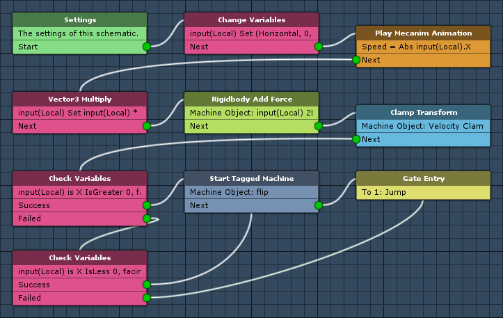
The following nodes are placed in layer 0: Base Layer. Layer 0 is the default layer.
Settings
We’ll add an audio clip resource to play a random jump sound effect.
Audio Clips
Click on Add Audio Clip Resource to add an audio clip resource.
- Name
Set to Jump. - Use Order
Select Random.
We need 3 audio clips, add the needed amount by clicking on Add Audio Clip.
- Audio Clip
Select Player-jump1 to Player-jump3.
The audio clips can be found at Assets/Tutorial Resources/Audio/Player/Jumps/.
Change Variables
Add > Value > Variable > Change Variables
We’ll use this node to store the player’s input into a Vector3 variable. The player can only move horizontally (left and right).
Click on Add Variable to add a variable change.
- Change Type
Select Variable. - Variable Key
Set to input. - Variable Origin
Select Local. - Type
Select Vector3. - Operator
Select Set. - Vector3 Type
Select Set Axis.
The X-axis will use the input from the Horizontal input key.
- X-Axis
Select Input Key Axis and Horizontal.
The Y and Z-axis will just be 0.
- Y-Axis, Z-Axis
Set to 0 (Value).
Play Mecanim Animation
Add > Animation + Audio > Mecanim > Play Mecanim Animation
This node is used to play an animation or set parameters of an animator. We’ll use it to play the walking animation of the player by setting the Speed float parameter.
- Object
Select Machine Object. - Play Mode
Select None.
We’ll play the animation by setting a parameter.
Click on Add Parameter to add an parameter that will be changed.
- Parameter Name
Set to Speed. - Parameter Type
Select Float. - Value
Select Vector3 Variable and X. - Variable Key
Set to Input. - Variable Origin
Select Local. - Math Function
Select Abs.
This will use the absolute value of the X-axis input, i.e. -1 will become 1.
Vector3 Multiply
Add > Value > Vector > Vector3 Multiply
We’ll use this node to multiply the input vector by the movement force of our player.
Variable Settings
- Variable Key
Set to input. - Variable Origin
Select Local. - Operator
Select Set.
Vector3 Value
- Vector3 Type
Select Vector3 Variable. - Variable Key
Set to input. - Variable Origin
Select Local.
Multiply By
- Multiply By
Set to 365 (Value).
Rigidbody Add Force
Add > Game Object > Rigidbody > Rigidbody Add Force
We’ll use this node to add the movement force to the player.
- Object
Select Machine Object. - Use 2D
Enable this setting.
We’ll use the input variable as force.
- Vector3 Type
Select Vector3 Variable. - Variable Key
Set to input. - Variable Origin
Select Local.
Clamp Transform
Add > Movement > Movement > Clamp Transform
We’ll use this node to limit the velocity of the player, otherwise he would just continue to get faster due to adding force to the rigidbody.
Clamp Object
- Object
Select Machine Object. - Value Origin
Select Velocity.
Clamp X-Axis
- Clamp X-Axis
Enable this setting. - X-Axis Minimum
Set to -5 (Value). - X-Axis Maximum
Set to 5 (Value).
Check Variables
Add > Value > Variable > Check Variables
We’ll use this node to check if the player is moving to the right but not facing right – in that case we’ll need to flip the sprite.
- Needed
Select All.
Click on Add Variable to add a variable condition.
- Condition Type
Select Variable. - Variable Key
Set to input. - Variable Origin
Select Local. - Is Valid
Enable this setting. - Exists
Enable this setting. - Type
Select Axis Vector3. - Axis
Select X. - Check Type
Select Is Greater. - Check Value
Set to 0 (Value).
Click on Add Variable to add another variable condition.
- Condition Type
Select Variable. - Variable Key
Set to facingRight. - Variable Origin
Select Object. - Object
Select Machine Object. - Is Valid
Disable this setting. - Exists
Enable this setting. - Type
Select Bool.
Check Variables
Add > Value > Variable > Check Variables
We’ll use this node to check if the player is moving to the left but facing right – in that case we’ll need to flip the sprite.
Copy the previous Check Variables node and connect the new node to the Failed slot of the previous node.
In the first variable condition, change the following settings.
- Check Type
Select Is Less.
In the 2nd variable condition, change the following settings.
- Is Valid
Enable this setting.
Start Tagged Machine
Add > Machine > Start Tagged Machine
We’ll use this node to start a tagged machine with the tag flip. This will flip the sprite for us – we’ll set up the schematic for this later.
This node is connected to the Success slots of both Check Variables nodes.
- Share Local Variables
Disable this setting. - Wait
Enable this setting.
Machine Object
- Object
Select Machine Object.
Starting Object
- Object
Select Machine Object.
Tag Settings
Click on Add Tag to add a starting tag.
- Tag
Set to flip.
Gate Entry (Layer Gate)
Next, we’ll add a Layer Gate node to the reach the next layer. This node is connected to the previous node’s Next slot and the 2nd Check Variables node’s Failed slot (i.e. when we’re moving left and already facing left).
Right click on the Next slot and select Add > Gate to Layer > Add New Layer. This will create a new layer and add a layer gate to it.
To display the new layer, either double click on the on the node’s title or select it in the layer popup field in the upper right corner of the editor.
You can rename the layer by clicking on the Rename Layer icon right of the popup field – e.g. name the layer Jump. Clicking on the icon again will stop editing the layer’s name.
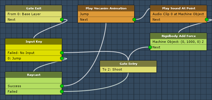
The following nodes are placed in layer 1: Jump. In this layer, we’ll handle the player’s jumping.
Input Key
Add > Input > Input Key
We’ll use this node to check if the player pressed the Jump input key.
This node is connected to the Next slot of the Gate Exit from layer 0.
- Input Key
Select Jump.
Raycast
Add > Game Object > Raycast
We’ll use this node to check if the player is on the ground by sending a raycast downwards. We don’t need to store any hit points or found game objects – this is just used to check if the ground is there.
This node is connected to the Jump slot of the Input Key node.
Raycast Settings
- Raycast Origin
Select Value Position.
We’ll fire the raycast from one position to another (Vector3 values). - Layer Mask
Select Ground.
To only select the Ground layer, select Nothing first.
The Start Position defines where the raycast will start.
- Vector3 Type
Select Game Object. - Object
Select Machine Object. - Value Origin
Select Position.
The Target Position defines where the raycast will be sent to.
- Vector3 Type
Select Game Object. - Object
Select Machine Object. - Child Object
Set to groundCheck.
This is a child game object of the player, slightly below the feet. - Value Origin
Select Position.
Play Mecanim Animation
Add > Animation + Audio > Mecanim > Play Mecanim Animation
We’ll use this node to play the player’s jump animation by setting the Jump trigger parameter.
This node is connected to the Success slot of the Raycast node.
- Object
Select Machine Object. - Play Mode
Select None.
Click on Add Parameter to add an parameter that will be changed.
- Parameter Name
Set to Jump. - Parameter Type
Select Trigger.
Play Sound At Point
Add > Animation + Audio > Audio > Play Sound At Point
We’ll use this node to play the jump sound at the current position of the player.
Position
- Vector3 Type
Select Game Object. - Object
Select Machine Object. - Value Origin
Select Position.
Audio Settings
- Audio Clip
Select Jump. - Wait
Disable this setting. - Volume
Set to 1 (Value).
Rigidbody Add Force
Add > Game Object > Rigidbody > Rigidbody Add Force
We’ll use this node to add the jumping force to the player.
- Object
Select Machine Object. - Use 2D
Enable this setting.
We’ll use the input variable as force.
- Vector3 Type
Select Set Axis. - X-Axis
Set to 0 (Value). - Y-Axis
Set to 1000 (Value). - Z-Axis
Set to 0 (Value).
Gate Entry (Layer Gate)
Finally, we’ll add a Layer Gate node to the reach the next layer. This node is connected to the previous node’s Next slot and the Failed slots of the Input Key and Raycast nodes.
Right click on the Next slot and select Add > Gate to Layer > Add New Layer. This will create a new layer and add a layer gate to it.
To display the new layer, either double click on the on the node’s title or select it in the layer popup field in the upper right corner of the editor.
You can rename the layer by clicking on the Rename Layer icon right of the popup field – e.g. name the layer Shoot. Clicking on the icon again will stop editing the layer’s name.
This layer will handle firing rockets, we’ll continue here at a later time. For now, this schematic is finished – click on Save Schematic and save it as PlayerControl in Assets/Schematics/.
Player Control: Tick Machine
The schematic handling the player’s control will try to start each frame, but will only be able to when the player is in control. We’ll stop the player control when the player died through changing the In Control game state.
Add a tick machine component to the hero game object (e.g. using the component menu: Makinom > Machines > Tick Machine) and change the following settings.
Start Settings
- Fixed Update
Enable this setting. - Check Game States
Enable this setting.
Click on Add Game State to add a game state condition.
- Condition Type
Select Game State. - Game State
Select In Control. - Check State
Select Active.
Machine Execution Settings
- Asset Type
Select Schematics. - Schematics Asset
Select PlayerControl. - Execution Type
Select Single. - Update Type
Select Fixed Update.
Flip: Schematic
Next, we’ll set up a simple schematic to flip a sprite.
Open the Makinom editor, navigate to Schematics and create a new schematic. Change the following settings.
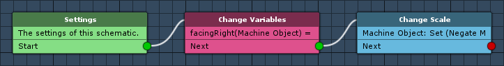
Change Variables
Add > Value > Variable > Change Variables
We’ll use this node to toggle the facingRight bool variable – toggling a bool will change true to false and false to true.
Click on Add Variable to add a variable change.
- Change Type
Select Variable. - Variable Key
Set to facingRight. - Variable Origin
Select Object. - Object
Select Machine Object. - Type
Select Bool.
To toggle the a bool variable, we’ll use itself as value and Negate it.
- Bool Type
Select Bool Variable. - Variable Key
Set to facingRight. - Variable Origin
Select Object. - Object
Select Machine Object. - Negate
Enable this setting.
Change Scale
Add > Movement > Movement > Change Scale
We’ll use this node to negate the X-axis scale – this will turn 1 to -1 and -1 to 1.
When working with 2D (sprites), flipping them is done by using negative scales.
Scaling Object
- Object
Select Machine Object.
Scale
- Vector3 Type
Select Set Axis.
The X-axis will be the negated current X-axis scale.
- X-Axis
Select Game Object and X. - Object
Select Machine Object. - Value Origin
Select Scale. - Math Function
Select Negate.
The Y-axis will be reset to the current Y-axis scale.
- Y-Axis
Select Game Object and Y. - Object
Select Machine Object. - Value Origin
Select Scale.
The Z-axis will be reset to the current Z-axis scale.
- Z-Axis
Select Game Object and Z. - Object
Select Machine Object. - Value Origin
Select Scale.
And that’s it for the schematic – click on Save Schematic and save it as Flip in Assets/Schematics/.
Take Damage: Tagged Machine
Finally, we’ll add the tagged machine handling flipping the sprite. Select the hero game object in the scene and add a tagged machine component to it (e.g. using the component menu: Makinom > Machines > Tagged Machine). Change the following settings.
Start Settings
Click on Add Starting Tag to add a tag that can start this machine.
- Starting Tag
Set to flip.
Machine Execution Settings
- Asset Type
Select Schematic. - Schematic Asset
Select Flip. - Execution Type
Select Single. - Update Type
Select Update.
And that’s it for now – apply the changes to the prefab by clicking on Apply (top of the inspector).
Don’t forget to save the scene.
Testing
Click on Play to test the game. You’ll be able to move the player around using the arrow keys and jump using the jump key.
The next tutorial will handle the camera and background.