
Setting up the procedural level generation.
In this tutorial we’ll set up schematics to generate the game level using sprite prefabs. We need 2 schematics, one for randomly spawning prefabs (walls, food, enemies) in the level and one for setting up the level.
Random Placement: Schematic
First, we’ll create the schematic to randomly place game objects in the level. The objects will be placed on fixed positions – to prevent having 2 objects at the same position, we’ll make use of variable lists storing the positions.
The Vector3 variable list will be filled in a different schematic – this schematic only handles spawning prefabs at the positions and removing the used position.
Open the Makinom editor, navigate to Schematics and create a new schematic. Change the following settings.

Settings
We need to define initialize a local variable and add a prefab resource.
Initial Local Variables
Click on Add Variable to add a variable change. Since this schematic will be used by tagged machines sharing local variables, we need to make sure the count is reset to 0 when the schematic starts.
- Change Type
Select Variable. - Variable Key
Set to count. - Variable Origin
Select Local. - Type
Set to Int. - Operator
Select Set. - Float Value
Set to 0 (Value).
Prefabs
We’ll be using the resource override to spawn different game objects with this schematic. Click on Add Prefab Resource to add a prefab resource.
There isn’t anything else to do – we’ll override the prefab in the tagged machines later.
Check Variables
Add > Value > Variable > Check Variables
This node will check for variable conditions. We’ll use it to check if the count reached the maximum, i.e. if we spawned all game objects we wanted to.
The objectCount variable defining the quantity of game objects we’ll spawn will be set by the tagged machines as local start variable.
Click on Add Variable to add a variable condition.
- Condition Type
Select Variable. - Variable Key
Set to count. - Variable Origin
Select Local. - Is Valid
Enable this setting. - Exists
Enable this setting. - Type
Select Int. - Check Type
Select Is Less. - Check Value
Select Int Variable. - Variable Key
Set to objectCount. - Variable Origin
Select Local.
Spawn Prefab
Add > Game Object > Prefab > Spawn Prefab
This node is used to spawn a prefab. We’ll use it to spawn a prefab at one of the Vector3 positions stored in the position local variable list.
- Prefab
Select Prefab 0. - Target Type
Select Position.
Position
- Vector3 Type
Select Vector3 Variable. - Variable Key
Set to position. - Variable Origin
Select Local List. - List Origin
Select Random.
A random value out of the list will be used. - Remove From List
Enable this setting.
The value will be removed from the list after we used it – this makes sure we don’t use the same position twice.
Change Variables
Add > Value > Variable > Change Variables
This node is used to change variables. We’ll use it to increase the count.
This node’s Next slot will be connected to the Check Variables node.
Click on Add Variable to add a variable change.
- Change Type
Select Variable. - Variable Key
Set to count. - Variable Origin
Select Local. - Type
Select Int. - Operator
Select Add. - Float Value
Select 1 (Value).
That’s it for the schematic – click on Save Schematic and save it as RandomPlacement in Assets/Schematics/.
Board Manager: Schematic
Next, we’ll create the schematic to set up the level. This schematic will fill the position list, create the floor and walls around the level, and start the tagged machines that’ll randomly place the other objects.
The level is set up using a defined number of rows and columns – they’ll be set up as local start variables of the machine. In the schematic, we’ll be going through the rows and columns field by field to generate positions and spawn prefabs.
The different tasks (filling the position list, creating floor and walls, randomply placing objects) will be set up on separate Node Layers. The node layer selection can be found in the upper right corner of the editor. You can connect node layers using Layer Gate nodes.
Create a new schematic and change the following settings.
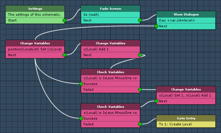
The following nodes are placed in layer 0: Base Layer. Layer 0 is the default layer.
Settings
We need to define 2 local start variables, initialize 2 local variables and 3 prefab resources.
Machine Start Variables
We’ll set up local variables as Machine Start Variable for easy setup in the machine component at a later time. When using the schematic in a machine component, the defined start variables will be added automatically, using their default values.
Click on Add Start Variable to add a local start variable that will be exposed to the machine component’s inspector.
- Variable Key
Set to columns. - Type
Select Int. - Default Value
Set to 8.
Copy the previous start variable and change the following setting.
- Variable Key
Set to rows.
Initial Local Variables
Click on Add Variable to add a variable change.
- Change Type
Select Variable. - Variable Key
Set to x. - Variable Origin
Select Local. - Type
Set to Int. - Operator
Select Set. - Float Value
Set to 1 (Value).
Copy the previous variable and change the following setting.
- Variable Key
Set to y.
Prefabs
We need 3 prefab resources – the outer walls, the floor and the exit. Click on Add Prefab Resource to add the first prefab resource.
- Name
Set to Outer Wall. - Use Order
Select Random.
We need 3 prefabs in this prefab resource, add the needed amount by clicking on Add Prefab.
- Prefab
Select OuterWall1, OuterWall2 and OuterWall3.
The prefabs can be found at Assets/Tutorial Resources/Prefabs/.
Click on Add Prefab Resource again to add another prefab resource.
- Name
Set to Floor. - Use Order
Select Random.
This time, we need 8 prefabs.
- Prefab
Select Floor1 to Floor8.
Click on Add Prefab Resource to add the last prefab resource.
- Name
Set to Exit.
There’s only one exit prefab, so we don’t need to add additional prefabs.
- Prefab
Select Exit.
Fade Screen
Add > UI > Fade Screen
This node is used to fade the screen. We’ll use it to initially set the screen to black when the game first starts.
- Wait
Enable this setting. - Time (s)
Set to 0. - Fade Alpha
Enable this setting. - Start Color
Select a black color without alpha (R=0, G=0, B=0, A=0). - End Color
Select a black color with full alpha (R=0, G=0, B=0, A=255).
Show Dialogue
Add > UI > Dialogue > Show Dialogue
This node is used to show a dialogue. We’ll use it to display the current day (level).
- Dialogue Type
Select Auto Close.
The dialogue will close automatically after some time. - GUI Box
Select Message. - Message (English)
Set to:
Day <var.int=level> - Block Accept Button
Enable this setting. - Close After (s)
Set to 1.5. - Wait
Enable this setting.
Change Variables
Add > Value > Variable > Change Variables
We’ll use this node to add a position (Vector3) based on the local variables x and y to the position list.
Click on Add Variable to add a variable change.
- Change Type
Select Variable. - Variable Key
Set to position. - Variable Origin
Select Local List. - List Change
Select Add. - Type
Select Vector3. - Operator
Select Set. - Vector3 Type
Select Set Axis.
The X-axis will use the local int variable x.
- X-Axis
Select Int Variable. - Variable Key
Set to x. - Variable Origin
Select Local.
The Y-axis will use the local int variable y.
- Y-Axis
Select Int Variable. - Variable Key
Set to y. - Variable Origin
Select Local.
The Z-axis isn’t used, so we just set it to 0.
- Z-Axis
Set to 0 (Value).
Change Variables
Add > Value > Variable > Change Variables
Now, we’ll increase the local variable y by 1.
Click on Add Variable to add a variable change.
- Change Type
Select Variable. - Variable Key
Set to y. - Variable Origin
Select Local. - Type
Select Int. - Operator
Select Add. - Float Value
Set to 1 (Value).
Check Variables
Add > Value > Variable > Check Variables
We’ll use this node it to check if y has reached the end of the row (local start variable rows).
This node’s Success slot is connected to the first Change Variables node (adding a new position into the list).
Click on Add Variable to add a variable condition.
- Condition Type
Select Variable. - Variable Key
Set to y. - Variable Origin
Select Local. - Is Valid
Enable this setting. - Exists
Enable this setting. - Type
Select Int. - Check Type
Select Is Less. - Check Value
Select Int Variable. - Variable Key
Set to rows. - Variable Origin
Select Local. - Math Function
Select Minus One.
This will use rows – 1 as value.
Change Variables
Add > Value > Variable > Change Variables
Now, we’ll increase the local variable x by 1 and reset y to 1.
This node is connected to the previous node’s Failed slot.
Click on Add Variable to add a variable change.
- Change Type
Select Variable. - Variable Key
Set to y. - Variable Origin
Select Local. - Type
Select Int. - Operator
Select Set. - Float Value
Set to 1 (Value).
Copy the previous variable change.
- Variable Key
Set to x. - Operator
Select Add.
Check Variables
Add > Value > Variable > Check Variables
After increasing x, we need to check if it reached the end of the column (local start variable columns).
This node’s Success slot is connected to the first Change Variables node (adding a new position into the list).
Click on Add Variable to add a variable condition.
- Condition Type
Select Variable. - Variable Key
Set to x. - Variable Origin
Select Local. - Is Valid
Enable this setting. - Exists
Enable this setting. - Type
Select Int. - Check Type
Select Is Less. - Check Value
Select Int Variable. - Variable Key
Set to columns. - Variable Origin
Select Local. - Math Function
Select Minus One.
This will use columns – 1 as value.
Gate Entry (Layer Gate)
Next, we’ll add a Layer Gate node to the reach the next layer. This node is connected to the previous node’s Failed slot.
Right click on the Failed slot and select Add > Gate to Layer > Add New Layer. This will create a new layer and add a layer gate to it.
To display the new layer, either double click on the on the node’s title or select it in the layer popup field in the upper right corner of the editor.
You can rename the layer by clicking on the Rename Layer icon right of the popup field – e.g. name the layer Create Level. Clicking on the icon again will stop editing the layer’s name.
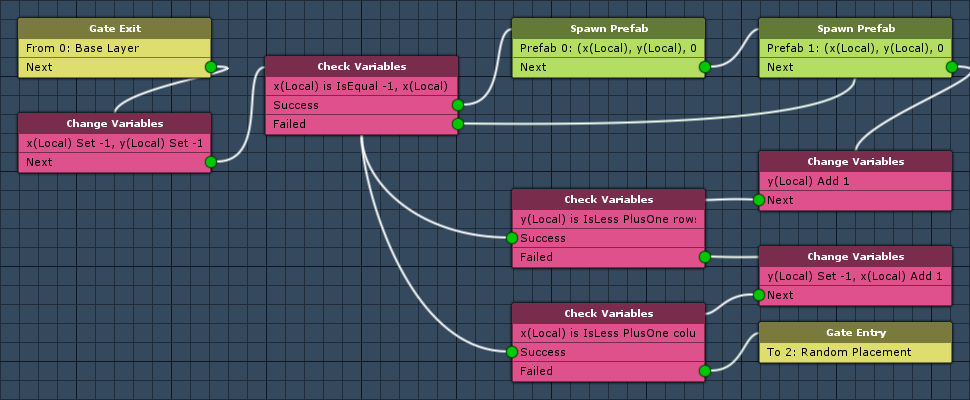
The following nodes are placed in layer 1: Create Level. In this layer, we’ll create the floor and walls around the level.
Change Variables
Add > Value > Variable > Change Variables
First, we’ll set x and y to -1, because we also need to place floor and walls around the actual level (rows/columns).
This node is connected to Next slot of the Gate Exit from layer 0.
Click on Add Variable to add a variable change.
- Change Type
Select Variable. - Variable Key
Set to x. - Variable Origin
Select Local. - Type
Select Int. - Operator
Select Set. - Float Value
Set to -1 (Value).
Copy the previous variable change.
- Variable Key
Set to y.
Check Variables
Add > Value > Variable > Check Variables
We’ll use this node to check if we’re at the outer edge of the level, i.e. if x or y are -1 or at their maximum (rows/columns)
- Needed
Select One.
Only one of the conditions needs to be true to be at the outer edge.
Click on Add Variable to add a variable condition.
- Condition Type
Select Variable. - Variable Key
Set to x. - Variable Origin
Select Local. - Is Valid
Enable this setting. - Exists
Enable this setting. - Type
Select Int. - Check Type
Select Is Equal. - Check Value
Set to -1 (Value).
Copy the previous variable condition and change the following settings.
- Check Value
Select Int Variable. - Variable Key
Set to columns. - Variable Origin
Select Local.
Again, copy the prevous variable condition.
- Variable Key
Set to y. - Check Value
Set to -1 (Value).
Again, copy the previous variable condition.
- Check Value
Select Int Variable. - Variable Key
Set to rows. - Variable Origin
Select Local.
Spawn Prefab
Add > Game Object > Prefab > Spawn Prefab
We’ll use this node to spawn an outer wall.
This node is connected to the Success slot of the previous node – i.e. the outer wall is spawned when we ware at the edge of the level.
- Prefab
Select Prefab 0: Outer Wall. - Target Type
Select Position.
Position
- Vector3 Type
Select Set Axis.
The X-axis will use the local int variable x.
- X-Axis
Select Int Variable. - Variable Key
Set to x. - Variable Origin
Select Local.
The Y-axis will use the local int variable y.
- Y-Axis
Select Int Variable. - Variable Key
Set to y. - Variable Origin
Select Local.
The Z-axis isn’t used, so we just set it to 0.
- Z-Axis
Set to 0 (Value).
Spawn Prefab
Add > Game Object > Prefab > Spawn Prefab
This time, we’ll spawn the floor. Copy the previous node and change the following settings.
- Prefab
Select Prefab 1: Floor.
Change Variables
Add > Value > Variable > Change Variables
Now, we’ll increase the local variable y by 1.
Click on Add Variable to add a variable change.
- Change Type
Select Variable. - Variable Key
Set to y. - Variable Origin
Select Local. - Type
Select Int. - Operator
Select Add. - Float Value
Set to 1 (Value).
Check Variables
Add > Value > Variable > Check Variables
We’ll use this node it to check if y has reached the outer edge (rows).
This node’s Success slot is connected to the first Check Variables node (checking if it’s an outer edge before spawning the prefabs).
Click on Add Variable to add a variable condition.
- Condition Type
Select Variable. - Variable Key
Set to y. - Variable Origin
Select Local. - Is Valid
Enable this setting. - Exists
Enable this setting. - Type
Select Int. - Check Type
Select Is Less. - Check Value
Select Int Variable. - Variable Key
Set to rows. - Variable Origin
Select Local. - Math Function
Select Plus One.
This will use rows + 1 as value.
Change Variables
Add > Value > Variable > Change Variables
Now, we’ll increase the local variable x by 1 and reset y to -1.
This node is connected to the previous node’s Failed slot.
Click on Add Variable to add a variable change.
- Change Type
Select Variable. - Variable Key
Set to y. - Variable Origin
Select Local. - Type
Select Int. - Operator
Select Set. - Float Value
Set to -1 (Value).
Copy the previous variable change.
- Variable Key
Set to x. - Operator
Select Add. - Float Value
Set to 1 (Value).
Check Variables
Add > Value > Variable > Check Variables
After increasing x, we need to check if it reached the end outer edge (columns).
This node’s Success slot is connected to the first Check Variables node (checking if it’s an outer edge before spawning the prefabs).
Click on Add Variable to add a variable condition.
- Condition Type
Select Variable. - Variable Key
Set to x. - Variable Origin
Select Local. - Is Valid
Enable this setting. - Exists
Enable this setting. - Type
Select Int. - Check Type
Select Is Less. - Check Value
Select Int Variable. - Variable Key
Set to columns. - Variable Origin
Select Local. - Math Function
Select Plus One.
This will use columns + 1 as value.
Gate Entry (Layer Gate)
Next, we’ll add a Layer Gate node to the reach the next layer. This node is connected to the previous node’s Failed slot.
Right click on the Failed slot and select Add > Gate to Layer > Add New Layer. This will create a new layer and add a layer gate to it.
To display the new layer, either double click on the on the node’s title or select it in the layer popup field in the upper right corner of the editor.
You can rename the layer by clicking on the Rename Layer icon right of the popup field – e.g. name the layer Random Placement. Clicking on the icon again will stop editing the layer’s name.
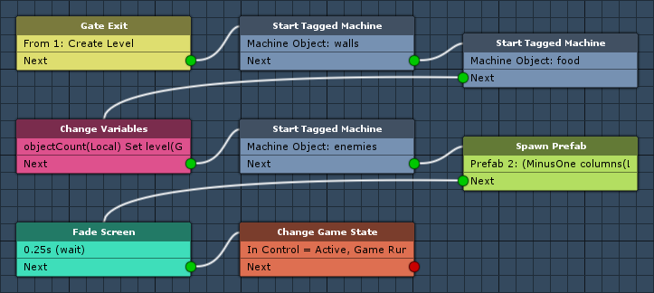
The following nodes are placed on layer 2: Random Placement. In this layer, we’ll start tagged machines, spawning the in-level walls, food and enemies.
Start Tagged Machine
Add > Machine > Start Tagged Machine
This node is used to start a tagged machine. We’ll use it to start a tagged machine with the tag walls, which will use the RandomPlacement schematic to randomly place walls in the level.
This node is connected to the Next slot of the Gate Exit from layer 1.
- Share Local Variables
Enable this setting. - Wait
Enable this setting.
Machine Object
- Object
Select Machine Object.
Starting Object
- Object
Select Machine Object.
Tag Settings
Click on Add Tag to add a starting tag.
- Tag
Set to walls.
Start Tagged Machine
Add > Machine > Start Tagged Machine
We’ll use this node to start a tagged machine with the tag food, which will use the RandomPlacement schematic to randomly place food in the level.
Copy the previous node and change the following settings.
- Tag
Set to food.
Change Variables
Add > Value > Variable > Change Variables
Before placing the enemies, we’ll set the objectCount for it in this schematic instead of the tagged machine as local start variables. The enemy count will be determined by the level used in a logarythmic calculation.
Click on Add Variable to add a variable change.
- Change Type
Select Variable. - Variable Key
Set to objectCount. - Variable Origin
Select Local. - Type
Select Int. - Operator
Select Set. - Float Value
Select Int Variable. - Variable Key
Set to level. - Variable Origin
Select Global.
Copy the previous variable change.
- Operator
Select Log. - Float Value
Set to 2 (Value).
Start Tagged Machine
Add > Machine > Start Tagged Machine
We’ll use this node to start a tagged machine with the tag enemies, which will use the RandomPlacement schematic to randomly place enemies in the level.
Copy one of the previous Start Tagged Machine nodes, connect it to the Change Variable node’s Next slot and change the following settings.
- Tag
Set to enemies.
Spawn Prefab
Add > Game Object > Prefab > Spawn Prefab
Now, we’ll spawn the exit at the upper right corner of the level (i.e. rows – 1 and columns – 1).
- Prefab
Select Prefab 2: Exit. - Target Type
Select Position.
Position
- Vector3 Type
Select Set Axis.
The X-axis will use the local int variable x.
- X-Axis
Select Int Variable. - Variable Key
Set to columns. - Variable Origin
Select Local. - Math Function
Select Minus One.
The Y-axis will use the local int variable y.
- Y-Axis
Select Int Variable. - Variable Key
Set to rows. - Variable Origin
Select Local. - Math Function
Select Minus One.
The Z-axis isn’t used, so we just set it to 0.
- Z-Axis
Set to 0 (Value).
Fade Screen
Add > UI > Fade Screen
Now it’s time to fade in the screen.
- Wait
Enable this setting. - Time (s)
Set to 0.25. - Fade Alpha
Enable this setting. - Start Color
Select a black color with full alpha (R=0, G=0, B=0, A=255). - End Color
Select a black color without alpha (R=0, G=0, B=0, A=0).
Change Game State
Add > Game > Game > Change Game State
This node is used to change game states. We’ll use it to activate Game Running and In Control.
The game states are used to trigger the roguelike game mechanics – waiting for the player’s input and moving the enemies afterwards. This will be handled by later schematics.
Click on Add Game State to add a game state change.
- Game State
Select In Control. - Set State
Select Active.
Click on Add Game State again to add another state change.
- Game State
Select Game Running. - Set State
Select Active.
And that’s it for this schematic – click on Save Schematic and save it as BoardManager in Assets/Schematics/.
The next tutorial will handle adding the level generation machines.