
Learn more about the node editor.
The node editor is part of the Makinom editor and is used to create schematics and formulas.
While this documentation focuses on schematics, most of the features are also available in formulas (unless mentioned otherwise).
The node editor is separated into 2 parts – the settings area and the node grid. The position of the settings area when editing schematics can be changed in the Makinom editor (Editor > Editor Settings) by the Schematic Editor Menu.
Settings Area #
The settings area displays the settings of the currently selected node.
Schematic Settings Area #
When editing schematics, the settings area also displays the editor help and buttons to create new schematics or open existing scematics. At the bottom of the editor you’ll find buttons to save or delete the schematic asset instead of the project save buttons. When using Save Schematic As … you can save an existing schematic using a new name.
Node Grid #
The node grid is used to add, move, connect and delete nodes. At the top of the node grid, you can see a button bar that is used to manage the nodes – you can also do this with the context menu (right mouse click).
You can navigate on the grid by clicking and dragging the scroll wheel (or middle mouse button).
Button Bar #
The button bar contains functionality to manage your nodes.
![]()
From left to right, the buttons are:
- Show Settings
Shows or hides the settings area. - Show Grid
Shows or hides the grid background. - Snap to Grid
Toggles if nodes will be placed neatly when moving them on and off. - Colorize Nodes
Toggles if nodes are colorized on and off.
The nodes are tintend using the colors defined in Editor > Editor Settings. - Enable/Disable Node
Toggles the checkbox to enable/disable nodes in the upper right corner of a node on or off. - Merge Single Slot
If enabled it’ll merge the info and slot of single slot nodes. - Sort Horizontally
Sorts the nodes horizontally from the selected node onwards.
If no node is selected, all nodes will be sorted starting from the Settings node (start node). - Sort Vertically
Sorts the nodes vertically from the selected node onwards.
If no node is selected, all nodes will be sorted starting from the Settings node (start node). - Place on Grid
Places all nodes neatly on the grid. - Add Node
Displays a menu to add nodes.
The nodes are separated into several sub-menus (e.g. Inputs, Machines, etc.).
If a node is selected, the node will be added as next node to the selected slot or the first free slot of the node.
If no node is selected, the node will be added without a connection. - Copy
Copies the selected node and adds it without a connection. - Copy to Clipboard
Copies the node to the clipboard. - Paste from Clipboard
Pastes the a node copied to the clipboard.
If a node is selected, the node will be added as next node to the selected slot or the first free slot of the node.
If no node is selected, the node will be added without a connection. - Paste Settings
Pastes the settings of a copied node on a selected node. - Remove Node
Removes the selected node. - Remove Chain
Removes the selected node and all following (connected) nodes. - +/- Slider
Zooms the node grid.
You can also zoom using the scroll wheel. - Search Bar
Allows searching for nodes by node name.
All non-matching nodes will be semi-transparent, making it easier to see the nodes you’re looking for. - Layer Selection
Allows changing the current layer, adding new layers or renaming a layer.
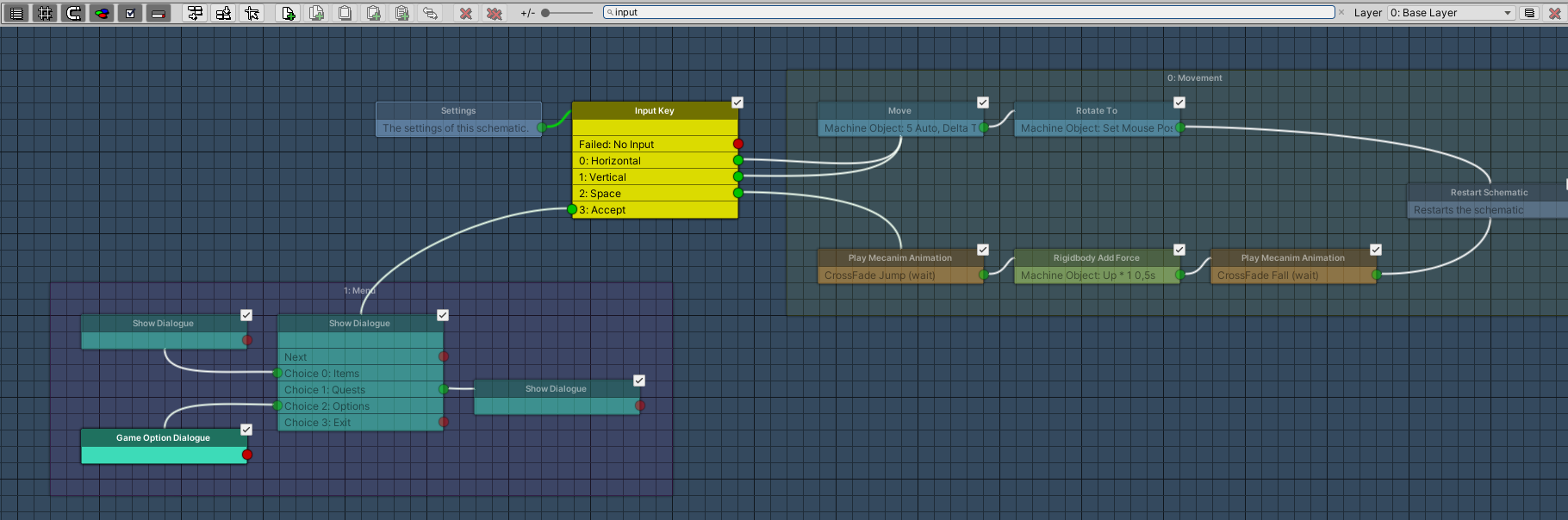
Searchable Nodes #
Looking for a specific node? Use the search bar to highlight nodes!
Zooming #
You can zoom in/out using the zoom slider in the button bar or the scroll wheel.

Node Layers #
The node layer selection is located at the right side of the button bar. You can use node layers to bring order into your schematic by separating them on different layers.
![]()
The node layer popup also allows adding new nodes by selecting Add New Node. You can change the name of a layer by clicking on the Rename Layer button on the right side of the popup – this changes the node layer popup into a text field. To stop editing the name, click on the Rename Layer button again.
To remove a layer, click on the Remove Layer button – this will remove the layer and all nodes (and layer gates) to it.
To connect nodes between layers, you can add Layer Gate nodes.
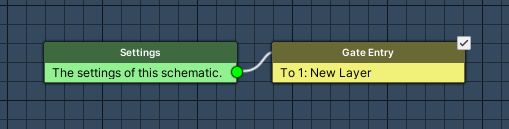
A Layer Gate node is visible on both layers that are connected by it. On the layer the connection starts, a Gate Entry node is displayed. On the layer the connection the connection ends, a Gate Exit node is displayed.
You can also move nodes and node changes between layers using the context menu.
Double clicking on a Gate Entry or Gate Exit title will take you to the layer it connects to.
Anatomy of a Node #
A node consists of 3 parts – title, info and slots.
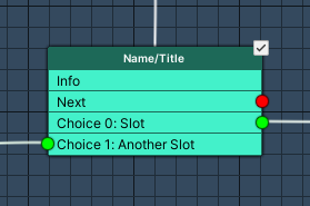
- Title
The name/title of the node is displayed at the top of the node (darker area of the node).
Double clicking on the node’s title will limit the node grid view to only display the node and following nodes (node chain).
To leave the limited view, either double click on the title again or double click somewhere on the grid.
Hovering the mouse above the title will display the help text of the node.
You can move the node by dragging it after clicking on the title. - Info
The info of the node displays parts of the settings made in the node.
The info text is displayed below the title – hovering the mouse above it will display the info text in the help text (displays more text). - Slots
The slots are used to connect nodes – depending on the node you’ll have 0, 1 or multiple slots.
A connected slot will have a green circle.
A not connected slot will have a red circle.
To change a node’s settings, select it by clicking on it. The settings area will display the node’s settings.
You might have noticed the small checkbox in the upper right corner of the node – this allows you to quickly enable or disable the node (the checkbox can be turned on/off in the button bar).
Connecting Nodes #
Nodes are connected by clicking and holding the left mouse button on a slot. Drag the line on another node and release the mouse button above the node. You can also double click on a slot and click on another node to connect them.
Connections can be removed through the context menu when right clicking on a slot and selecting Remove Connection.
Context Menu #
The context menu is opened by a click on the right/context mouse button. Depending on where you’ve clicked, you will have different options available.
Like the all other popups, the node editor’s context menu is also searchable.
Click on Grid #
Right clicking on the grid will allow:
- Adding nodes without connecting them.
- Adding node groups.
- Paste a node from the clipboard (works like adding a new node).
- Sort all nodes horizontally or vertically.
- Snap all nodes to the grid.
Click on Node #
Right clicking on a node (title/info) will allow:
- Adding nodes connected to the first free slot of the node.
When there is no free slot, connects the node to the first slot and the previously connected node to the new node’s first slot. - Add the node to a new or existing node group.
- Copy the node or copy it to the clipboard.
- Paste a node or node settings from the clipboard.
- Removing the node or node chain.
- Sorting the node and all following nodes (chain) horizontally or vertically.
- Snap the node and all following nodes (chain) to the grid.
- Move the node and all following nodes to a different node layer.
This will automatically create a Layer Gate node and connect it to the previous node. - Limit the node view (same as double clicking on the title) or view all nodes.
Click on Slot #
Right clicking on a slot will allow:
- Adding nodes connected to the slot.
When there already is a connection, the new node will be connected to the slot and the previously connected node to the new node’s first slot. - Add the node to a new or existing node group.
- Copy the node or copy it to the clipboard.
- Paste a node or node settings from the clipboard.
- Removing the slot’s connection.
- Removing the node or node chain.
- Sorting the node and all following nodes (chain) horizontally or vertically.
- Snap the node and all following nodes (chain) to the grid.
- Move the node and all following nodes to a different node layer.
This will automatically create a Layer Gate node and connect it to the previous node. - Limit the node view (same as double clicking on the title) or view all nodes.
Box Selection #
You can use box selection to select multiple nodes.
Using Shift+Click also lets you select multiple nodes.
Node Groups #
Use Node Groups to bring order into your node-chaos. You can also put groups into groups, into groups, into groups …
You can add or remove nodes (and groups) to/from groups by holding CTRL while dragging them – or use the context menu.
Keyboard Shortcuts #
There are several keyboard shortcuts available:
- CTRL+F
Focus on the search field. - CTRL+D
Duplicate a node. - CTRL+C
Copy a node to the clipboard. - CTRL+V
Paste a node from the clipboard. - CTRL+X
Cut (i.e. copy to clipboard and remove) a node. - CTRL+G
Create a node group (adding selected nodes to it). - F
Focus/scroll on the selected node(s). - Delete
Delete the selected nodes.
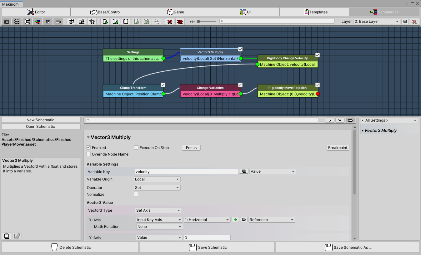
Live Debugging (Schematics only) #
Want to know what your running schematics are doing? Try live debugging them and see which nodes are executed, the values they’re using and which variable changes they cause.
Debug information will be collected when the Makinom editor is open while playing. You can also enable Auto Debug Schematics in Editor > Editor Settings > Node Editor Settings to always collect the debug information, even if the editor is closed.
Debugging is only used when playing in the Unity editor, i.e. built games are not impacted by it.
You can directly start debugging a machine’s schematic by clicking on the Edit Schematic button in the machine’s inspector while it’s running. Having a schematic open in the node editor will also list all available running or already stopped schematics that are using the same schematic asset.
See the image (and explanations) below for more details on the debugging features.

- 1) Debugging Available
Lists all available schematics (running and already stopped) for the open schematic asset.
Start/stop debugging via the button of each entry. - 2) Debug Info
When having a node selected, the debug info shows if the node has already been executed (and at which index) and the variable changes the node caused.
If the node has a wait time, it’ll also show this information. - 3) Debug Value
Shows the debug value(s) of string, float, bool and Vector3 value selections. - 4) Executed Node
Nodes that have already been executed are marked with a yellow border.
The color can be changed in Editor > Editor Settings. - 5) Current Node
The node the execution is currently at is marked with an orange border.
The color can be changed in Editor > Editor Settings. - 6) Breakpoint
Nodes that have a breakpoint set will be marked with a red circle in their upper left corner.
You can set a breakpoint via the Breakpoint button in the node’s settings.
Unity will pause when reaching a breakpoint node – due to the fast execution between nodes, that might still execute additional nodes after the breakpoint node until Unity paused the game.
You can also change the schematic while it’s running, e.g. changing a connection or adding/removing nodes. This’ll change all schematics that use the same asset, not just the one you’re currently debugging. To make the changes permanent, you need to save the schematic.
Please note that exiting play mode (i.e. stopping the game in the Unity editor) will lead to losing the debug values once you open a different schematic asset.


